
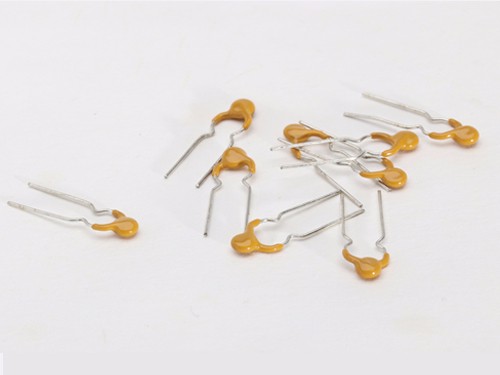
PPTC Resettable Radial-leaded Fuse
Brand : Songshan
Product origin : Shanghai
Delivery time : 7-15 days
Supply capacity : 15000000
Basic Info
Model No.: LP16-400DF
Breaking Capacity: Low
Type: Current Fuse
Usaga: Low Voltage
Shape: SMD
Fusing Speed: F
Additional Info
Packaging: Carton
Brand: Songshan
Transportation: Ocean,Land,Air
Place of Origin: Shanghai,China
Product Description
LP16-400DF, a kind of polymer resettable fuse is made of polymer materials with conductivity, thus the rated current is produced. If the current through the fuse is too high, its temperature will continue to rise, at the same time polymer material will swell, causing the resistance to rise, thus the current in the circuit is reduced effectively. The fuse will return to its original state to ensure the normal use of the circuit when the fault is removed. The fuse can play the role of a general fuse in electrical properties. Hence in many cases such kind of resettable fuse already replaced the conventional fuse.
Features
Customized size and electrical characteristic available
Radial-leaded devices for wave-soldering or manually assembly
Fast tripping resettable circuit protection
Product Dimensions For Radial-leaded Devices
Unit: mm
Part number
| Dimension | |||||
A | B | C | D | E | Figures for | |
Max. | Max. | Max. | Min. | Min. | Dimension | |
LP16-400DF | 12.1 | 13.5 | 5.1 | 3.5±0.6 | 3.0 | Fig.6 |

Thermal Derating Chart-IH(A)
Part number
| Hold current | ||||||||
-40℃ | -20℃ | 0℃ | 25℃ | 40℃ | 50℃ | 60℃ | 70℃ | 85℃ | |
LP16-400DF | 5.9 | 5.3 | 4.8 | 4.0 | 3.5 | 3.2 | 2.8 | 2.5 | 1.9 |
Electrical Characteristics at 25℃
Part number
| IH | IT | Vmax | Imax | Max. Time-to-trip | Pd typ | Rmin | R1max | Figures for | |
(A) | (A) | (V) | (A) | (A) | (S) | (W) | (Ω) | (Ω) | Dimension | |
LP16-400DF | 4.00 | 6.80 | 16 | 100 | 20.00 | 3.5 | 2.4 | 0.020 | 0.063 | Fig.6 |
IH=Hold current: maximum current at which the device will not trip at 25℃ still air.
IT=Trip current: minimum current at which the device will always trip at 25℃ still air.
Vmax=Maximum voltage device can withstand without damage at rated current.
Imax=Maximum fault current device can withstand without damage at rated voltage.
Ttrip=Maximum time to trip at assigned current.
Pdtyp=Typical power dissipation: typical amount of power dissipated by the device when in state air environment.
Rmin=Minimum device resistance at 25℃ prior to tripping.
R1max=Maximum device resistance measured after 1 hour post one-time trip.
Part Numbering System

Test Procedures And Requirements
Test | Test Conditions | Accept/Reject Criteria |
Resistance | In still air @ 25℃ | Rmin≤R≤Rmax |
Time to Trip | Specified current, Vmax, 25℃ | T≤maximum Time to Trip |
Hold Current | 30min, at IH | No trip |
Trip Cycle Life | Vmax, Imax, 100cycles | No arcing or burning |
Trip Endurance | Vmax, 24hours | No arcing or burning |
Application Requirements
Soldering recommendation:
* Methods: IR, Vapor phase oven, hot air oven, wave solder, soldering temperature should not exceed GB-T2423 request.
* Devices can be cleaned using standard industry methods and solvents.
Notes:
If reflow temperatures exceed the recommended profile, devices may not meet the performance requirements.
Storage:
The maximum ambient temperature shall not exceed 40℃. Storage temperatures higher than 40℃ could result in the deformation of packaging materials. The maximum relative humidity recommended for storage is 70%. High humidity with high temperature can accelerate the oxidation of the solder plating on the termination and reduce the solderability of the components. Sealed plastic bags with desiccant shall be used to reduce the oxidation of the termination and shall only be opened prior to use. The products shall not be stored in areas where harmful gases containing sulfur or chlorine are present.
Warning:
PPTC devices are intended for protection against occasional over-current or over-temperature fault conditions, and should not be used when repeated fault conditions are anticipated. Operation beyond maximum ratings or improper use may result in device damage and possible electrical arcing and flame.
Notes:
The specification is intended to present application, product and technical data to assist the user in selecting PPTC circuit production devices. However, users should independently evaluate and test the suitability of each product. Wayon makes no warranties as to the accuracy or completeness of the information and disclaims any liability resulting from its use. Wayon`s only obligations are those in the Wayon Standard Terms and Conditions of Sale and in no case will Wayon be liable for any incidental, indirect, or consequential damages arising from the sale, resale, or misuse of its products. Wayon reserves the right to change or update, without notice, any information contained in this specification.